


EMI Shielding Products
- Custom Gasket Fabrication
- Connector Gaskets
- Bonded O Ring
- Custom Gaskets
- Conduct-O-Knit Knitted Wire Mesh
- Conduct-O-Seal Combo Gasket
- Conduct-O-Elastomer
- Conduct-O-Seal Oriented Wire in Silicone Gasket Material
- Conduct-O-Mesh Tape
- Conduct-O-Foam
- Conduct-O-Bond
- Optical Filters For Electronic Displays
- Shielded Vent Panels
- 300 Series
Why High-Frequency EMI Shielding Failures Are Showing Up in Testing
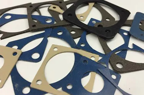
Automotive and aerospace engineers are facing an uncomfortable surprise this year. Components that passed compliance testing at 2 GHz are failing when swept up to 6 GHz. Seams, fastener spacing, and even small vent openings that once looked safe are now leaking interference. With production schedules and certification deadlines on the line, these late-stage failures are more than a technical annoyance; they threaten launch dates and budgets.
This shift is happening because UN R10 Rev.7, now in effect, raises radiated immunity requirements to 6 GHz. Designs that were compliant a year ago can fall short today. Shielding strategies built around older limits don’t always hold up at higher frequencies. The practical solution is to re-evaluate openings, joints, and gaskets so they block energy in the 3 to 6 GHz range.
What Makes High-Frequency EMI Shielding Harder to Control?
When signals climb into the gigahertz range, the rules change. Openings behave like antennas, seams that seemed tight begin to radiate, and even small contact resistance at joints allows leakage. A vent hole that was harmless at 1 GHz may fail at 5 GHz because the wavelength is shorter and the margin for error is smaller.
For manufacturers, this means that designs must be judged against higher-frequency behavior. A seam that looks solid on CAD drawings may actually function like a slot antenna once built. Understanding this shift is critical if teams want to pass compliance without redesign delays.
How to Size Gaps and Fastener Spacing for 6 GHz
The longest dimension of any opening determines how much energy leaks through it. At 6 GHz, the wavelength is roughly 50 millimeters, so keeping openings below one twentieth of that — about 2.5 millimeters — helps ensure shielding effectiveness. Many teams push further, targeting below 1 millimeter for seams.
- Seams and slots: Keep gaps as short as possible. Long, narrow slots leak more than small, round holes.
- Vent patterns: Use staggered small holes or honeycomb designs instead of elongated cuts.
- Fastener spacing: Place screws or compression points closer together so joints don’t behave like slots between contact points.
Each of these steps directly reduces the chance of leakage when your design is tested at higher frequencies.
Why Gasket Contact Resistance Matters More Now
A seam’s geometry is only half the equation. At gigahertz frequencies, the quality of electrical contact is just as critical. If oxide buildup, coating layers, or uneven pressure increase resistance at a joint, high-frequency currents can slip through.
To avoid this, do the following:
- Prepare surfaces so metal meets metal wherever possible.
- Use conductive finishes or mask coating in gasket lands.
- Select gaskets that maintain uniform pressure and stable micro-contacts over the product’s life.
When those conditions are met, seams behave more like continuous conductors instead of radiating slots.
How to Build Testing Into the Design Phase: Demand the Best from EMI Shielding
Waiting until certification testing to find a problem is costly. Pre-compliance checks can catch weak spots early. Near-field scanning of prototypes helps identify leaking seams or cutouts before the chamber test. Building sample fixtures with real fastener spacing and coatings ensures that lab results reflect production reality.
Planning around the specific test method also matters. Some labs use anechoic chambers, while others use reverberation chambers. Reverberation chambers create a more uniform field and can expose weaknesses that directional testing may miss. Confirming test methods and levels up front prevents surprises.
A Practical Next Step for EMI Shielding Reliability
The extension of immunity testing to 6 GHz means shielding details that were once “good enough” now require closer attention. Small seams, fastener spacing, and gasket resistance are the differences between a pass and a redesign.
East Coast Shielding works with manufacturers to close those gaps — from reviewing drawings for high-frequency leakage risks to supplying gaskets and board-level shields that hold contact through vibration and thermal cycles. If your team is preparing for UN R10 Rev.7 testing, the right time to review your shielding is now.